section1
编辑section1-实验笔记
1.1 需求堆叠模拟器没有办法实现。LACP 接口编号不同。
1.2 需求配置设备互联 IP 的时候,Export 的 IP 地址可以使用 vlanif。
1.3 需求与真机配置相同。
1.4 需求与真机配置相同。
1.5 需求与真机配置相同。
1.6 需求汇聚交换机的 802.1× 接入模板、MAC 接入模板、认证模板模拟器不存在命令。
AP 不认证模拟器不存在命令。
Vlan pool 不存在命令。
1.7 需求交换机的策略路由没有办法配置,或者通过流策略配置之后是不生效的。
设备密码相关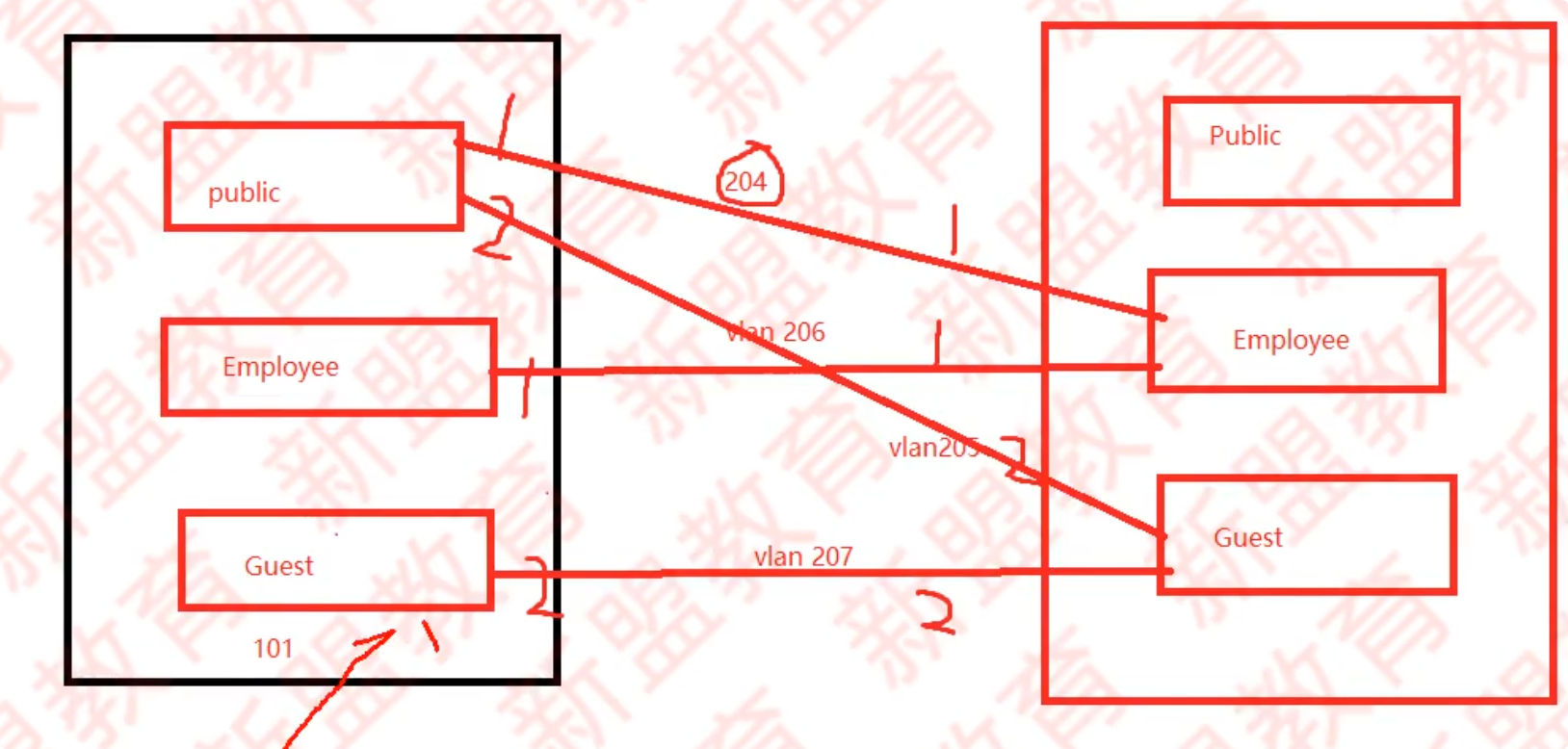
1.1 网络可靠性
display stack configuration:查看堆叠配置
display stack:查看堆叠口的各项数据
lldp enabk:路层发现协议 LLDP 开启,开机以后要敲一个
1.1.1 T2 汇聚堆叠部署
在 X_T2_AGG1_1 上进行堆叠配置
stack slot 0 priority 120 renumber 0
interface stack-port0/1
port interface XGigabitEthernet 0/0/1 enable
Y
interface stack-port 0/2
port interface XGigabitEthernet 0/0/2 enable
Y
在 X_T2_AGG1_2 进行堆叠配置
stack slot 0 priority 100 renumber 1
interface stack-port 0/1
port interface XGigabitEEthernet 0/0/2 enable
Y
port interface stack-port 0/2
port interface GigabitEthernet 0/0/1 enable
Y
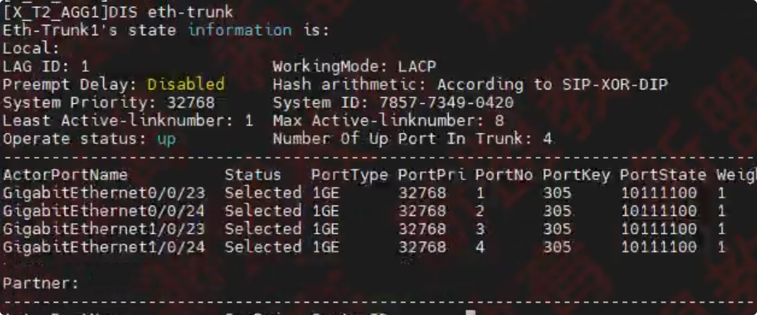
1.1.2 X_T2_AGG1 交换机与 X_T1_CORE1 以及接入交换机之间部署链路聚合
- 工作模式选择 LACP 模式,设备间所有物理连接均作为成员连路且两端的接口必须处于选中状态
- X_T2_AGG1 与接入交换机之间的物理连接已完成,但连路互联信息因故丢失,需自行获取
在 X_T2_AGG1 , X_T2_ACC1 , X_T2_ACC2, core1 开启 LLDP
lldp enable
X_T1_CORE1 配置链路聚合
interface Eth-Trunk2
port link-type trunk
port trunk allow-pass vlan 100 209
mode lacp
#             模拟器上是    0/0/17 0/0/18 0/0/19 0/0/20
trunkport GigabitEthernet 0/0/21 0/0/22 0/0/21 1/0/22
X_T2_AGG1 配置链路聚合
display lldp neighbor brief 查看下行聚合接口
interface Eth-trunk 1
port link-type trunk
port trunk allow-pass vlan 100 209
mode lacp
# 模拟器上是 0/0/21 0/0/22 0/0/23 0/0/24
trunkport GigabitEthernet 0/0/23 0/0/24 1/0/23 1/0/24
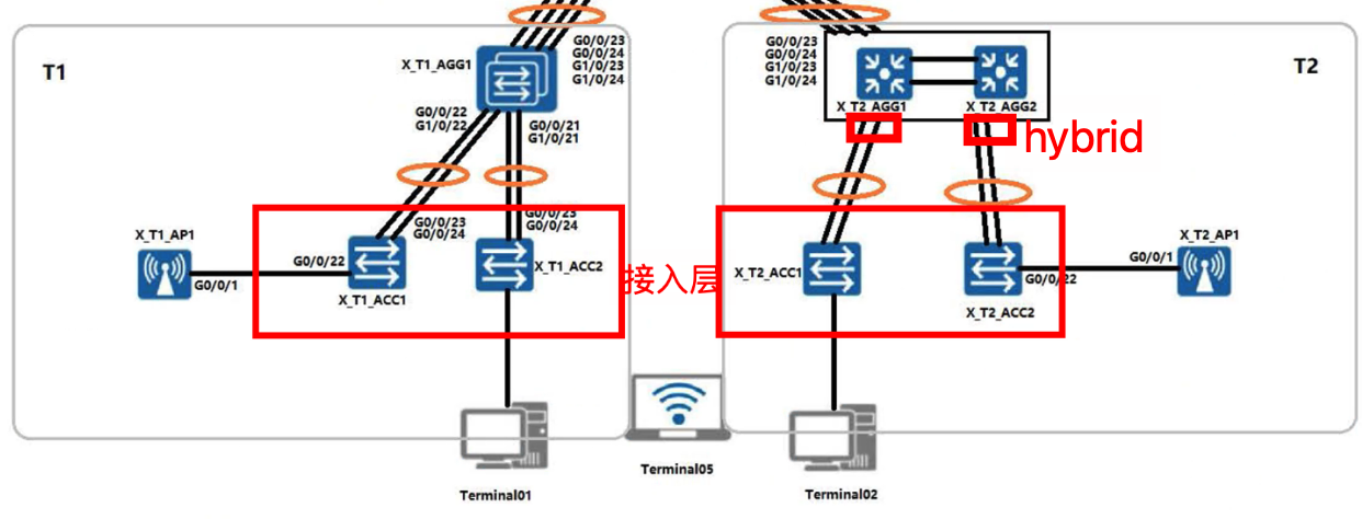
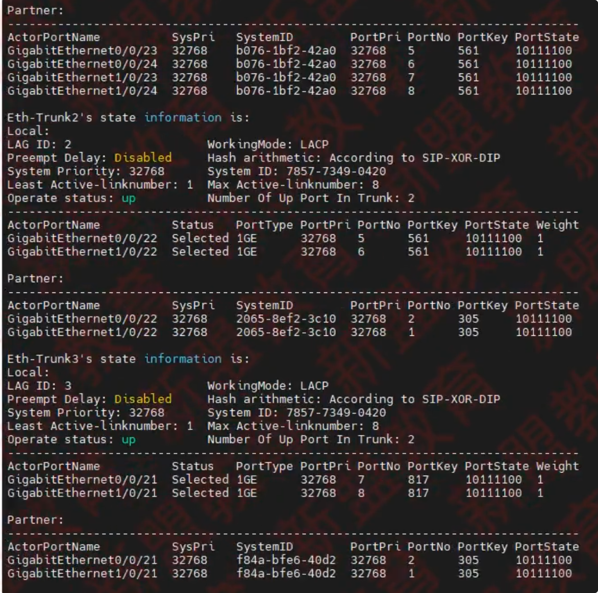
interface Eth-trunk 2
port link-type hybrid
port hybrid tagged vlan 100
mode lacp
# 模拟器上是 0/0/19 0/0/20
trunkport GigabitEthernet 0/0/21 0/0/22
interface Eth-trunk 3
port link-type hybrid
port hbyrid tagged vlan 100
mode lacp
# 模拟器上是 0/0/17 0/0/18
trunkport GigabitEthernet 0/0/21 0/0/22
X_T2_ACC1 和 X_T2_ACC2 配置链路聚合
vlan batch 100
interface Eth-trunk 1
port link-type trunk
port trunk allow-pass vlan 100
mode lacp
trunkport GigabitEthernet 0/0/23 0/0/24
做完或在汇聚上检查一下
display eth-trunk
1.2 基础业务
需求 1.2.1
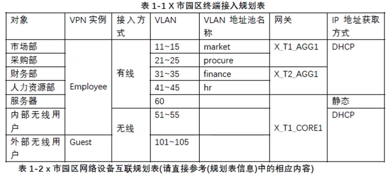
根据所在部门、接入方式、终端类型等因素将终端用户划分成 7 类对象,参考表 1-1《X 市园区终端接入规划表》
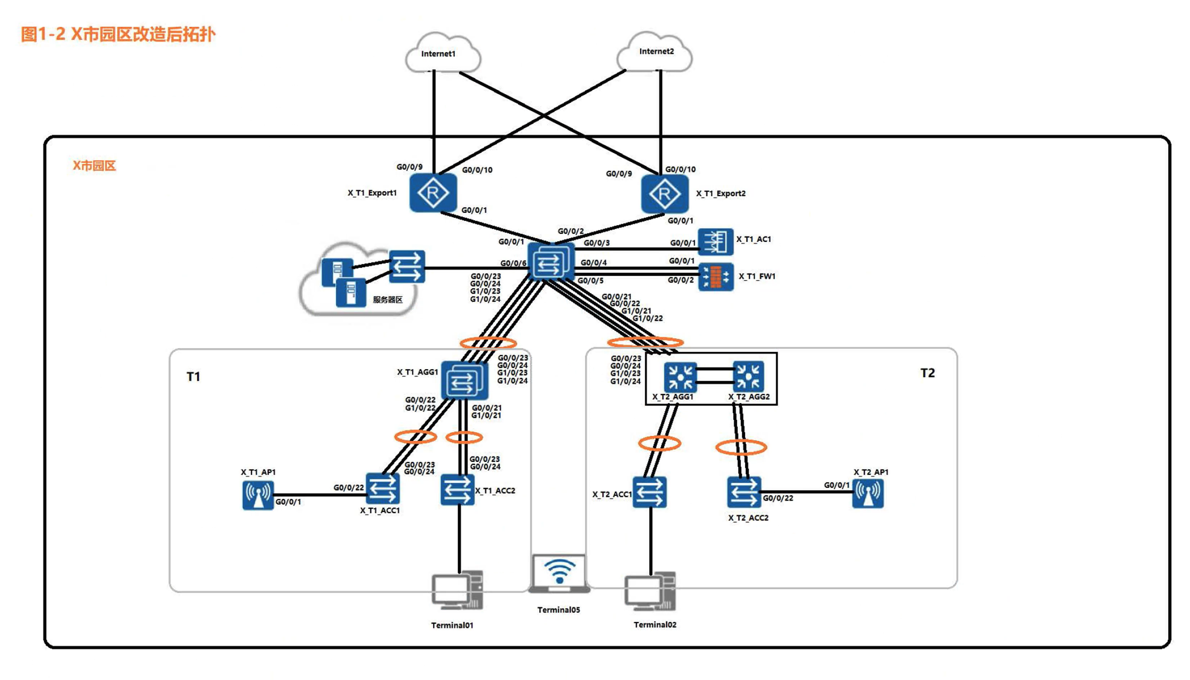
- 市场部、采购部用户从 X_T1_ACC1 和 X_T1_ACC2 的 GE0/0/1-GE0/0/20 接入网络。
财务部、人力资源部用户从 X_T2_ACC1 和 X_T2_ACC2 和 GE0/0/1-GE0/0/20 接入网络 - 除服务器外,其他所有用户均通过 DHCP 获取 IP 地址与网关地址信息,X_T1_CORE1 设备为 DHCP 服务器(所有 DHCP 地址池已经创建完成)
- 网关设备均以 VLANIF 接口作为用户网关,IP 地址为 10.1.x.254/24,x 为用户所属的 VLAN
1.1 从哪里接入不是配置人决定的,所以不需要做,1.2 已经创建完成,所以这里只需要做 1.3 就可以
1.2 需求配置设备互联 IP 的时候,Export 的 IP 地址可以使用 vlanif。
X_T1_AGG1 创建 vlan,配置网关地址(市场部,采购部)
vlan batch 11 to 15 21 to 25
interface vlanif 11
ip address 10.1.11.254 24
interface vlanif 12
ip address 10.1.12.254 24
interface vlanif 13
ip address 10.1.13.254 24
interface vlanif 14
ip address 10.1.14.254 24
interface vlanif 15
ip address 10.1.15.254 24

interface vlanif 21
ip address 10.1.21.254 24
interface vlanif 22
ip address 10.1.22.254 24
interface vlanif 23
ip address 10.1.23.254 24
interface vlanif 24
ip address 10.1.24.254 24
interface vlanif 25
ip address 10.1.25.254 24
X_T2_AGG1 创建 vlan,配置网关地址(财务,人力)
vlan batch 31 to 35 41 to 45

interface vlanif 31
ip address 10.1.31.254 24
interface vlanif 32
ip address 10.1.32.254 24
interface vlanif 33
ip address 10.1.33.254 24
interface vlanif 34
ip address 10.1.34.254 24
interface vlanif 35
ip address 10.1.35.254 24

interface vlanif 41
ip address 10.1.41.254 24
interface vlanif 42
ip address 10.1.42.254 24
interface vlanif 43
ip address 10.1.43.254 24
interface vlanif 44
ip address 10.1.44.254 24
interface vlanif 45
ip address 10.1.45.254 24
X_T1_CORE1 创建 vlan,配置网关地址
vlan batch 51 to 55 101 to 105
interface vlanif 51
ip address 10.1.51.254 24
interface vlanif 52
ip address 10.1.52.254 24
interface vlanif 53
ip address 10.1.53.254 24
interface vlanif 54
ip address 10.1.54.254 24
interface vlanif 55
ip address 10.1.55.254 24

interface vlanif 101
ip address 10.1.101.254 24
interface vlanif 102
ip address 10.1.102.254 24
interface vlanif 103
ip address 10.1.103.254 24
interface vlanif 104
ip address 10.1.104.254 24
interface vlanif 105
ip address 10.1.105.254 24
需求 1.2.2
根据已有设备配置并结合《X 市园区终端接入规划表》中的内容完成设备互联配置
X_T1_Export1
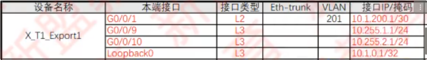
# 考试二层口  模拟器为三层直接配,模拟器此处接口为6/0/1
interface GigabitEthernet 0/0/1
port link-type access
port default vlan 201
X_T1_Export2

sysname X_T1_Export2

vlan 202
interface vlanif 202
ip address 10.1.200.5 30

# 考试二层口  ,模拟器为三层直接配,模拟器此处接口为6/0/1
interface GigabitEthernet 0/0/1
port link-type access
port default vlan 202

interface loopback 0
ip address 10.1.0.2 32
X_T1_Core1
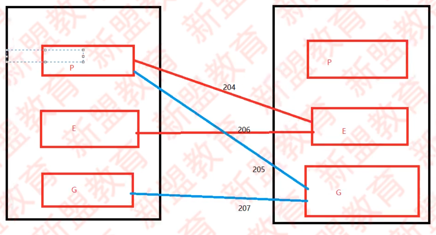
此处有坑,并不是按照表上配,而是 g0/0/4 配置 204、206,g0/0/5 配置 205、207
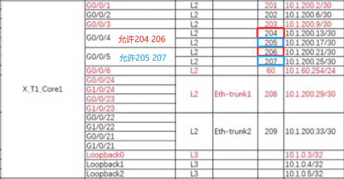
vlan batch 201 to 209
interface vlanif 201
ip address 10.1.200.2 30
interface vlanif 202
IP add 10.1.200.6 30
interface vlanif 203
ip address 10.1.200.9 30
interface vlanif 204
ip address 10.1.200.13 30
interface vlanif 205
ip address 10.1.200.17 30
interface vlanif 206
ip address 10.1.200.21 30
interface vlanif 207
ip address 10.1.200.25 30
interface vlanif 208
ip address 10.1.200.29 30
interface vlanif 209
ip address 10.1.200.33 30

interface loopback 1
ip address 10.1.0.4 32
interface loopback 2
ip address 10.1.0.5 32

interface GigabitEthernet 0/0/2
port link-type access
port default vlan 202

interface GigabitEthernet 0/0/4
port link-type trunk
port trunk allow-pass vlan 204 206
undo port trunk allow-pass vlan 1

interface GigabitEthernet 0/0/5
port link-type trunk
port trunk allow-pass vlan 205 207
undo port trunk allow-pass vlan 1
X_T1_AGG1
由于 Trunk(预配)不能做 VLAN 混合接入,因而 Eth-trunk 2/3 需要改成 Hybrid,禁用 vlan100
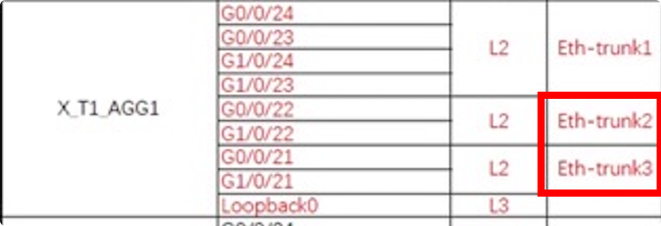
interface Eth-Trunk2
 undo port trunk allow-pass vlan 100
 port link-type hybrid
 port hybrid tagged vlan 100
 mode lacp
#
interface Eth-Trunk3
 undo port trunk allow-pass vlan 100
 port link-type hybrid
 port hybrid tagged vlan 100
 mode lacp
X_T2_AGG1
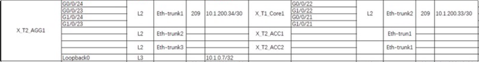
vlan batch 100 209
interface vlanif 209
ip address 10.1.200.34 30

interface loopback 0
ip address 10.1.0.7 32
X_T1_FW1
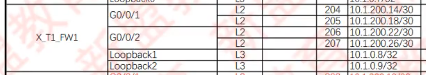
g1/0/1 放行 204 206, g1/0/2 放行 205 207
sys X_T1_FW1

vlan batch 204 to 207

interface vlanif 204
ip address 10.1.200.14 30
interface vlanif 205
ip address 10.1.200.18 30
interface vlanif 206
ip address 10.1.200.22 30
interface vlanif 207
ip address 10.1.200.26 30

interface loopback 1
ip address 10.1.0.8 32
interface loopback 2
ip address 10.1.0.9 32

interface GigabitEthernet 1/0/1
portswitch
port link-type trunk
port trunk allow-pass vlan 204 206
undo port trunk allow-pass vlan 1

interface GigabitEthernet 1/0/2
portswitch
port link-type trunk
port trunk allow-pass vlan 205 207
undo port trunk allow-pass vlan 1
需求 1.2.3.1
所有三层设备之间部署多区域 OSPF
- 两台出口路由器与 核心交换机之间的链路属于骨干区域,终端用户访问 Internet 流量由两台出口路由器共同分担
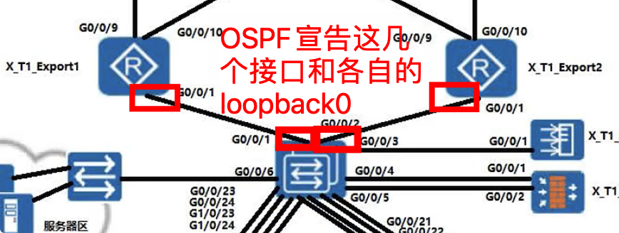
在 X_T1_Export1 上配置 OSPF
ospf 1 router-id 10.1.0.1
# 缺省路由通告
default-route-advertise
arer 0
network 10.1.0.1 0.0.0.0
network 10.1.200.1 0.0.0.0
在 X_T1_Export2 上配置 OSPF
ospf 1 router-id 10.1.0.2
default-route-advertise
arer 0
network 10.1.0.2 0.0.0.0
network 10.1.200.5 0.0.0.0
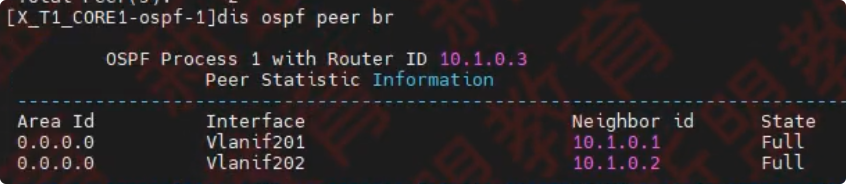
在 X_T1_Core1 上配置 OSPF
ospf 1 router-id 10.1.0.3
area 0
network 10.1.0.3 0.0.0.0
network 10.1.200.2 0.0.0.0          201
network 10.1.200.6 0.0.0.0          202
display ospf peer brief
需求 1.2.3.2
根据网络隔离需求,将内部网络与访客网络分别划到 OSPF 的区域 1 和区域 2
在 Core1 上配置 OSPF 与 FW1、X_T1_AGG1、X2_AGG1、的 OSPF 对接
# OSPF 1 与Firewall对接
ospf 1
# Vlanif204
area 1
network 10.1.200.13 0.0.0.0
# VLANif205
area 2
network 10.1.200.17 0.0.0.0

# OSPF 2 area 1与企业端设备对接
ospf 2 router-id 10.1.0.4 vpn-instance Employee
# Employee在area 1
area 1
network 10.1.0.4 0.0.0.0
# 51~55、60
network 10.1.51.254 0.0.0.0
network 10.1.52.254 0.0.0.0
network 10.1.53.254 0.0.0.0
network 10.1.54.254 0.0.0.0
network 10.1.55.254 0.0.0.0
network 10.1.60.254 0.0.0.0
# 206、208、209
network 10.1.200.21 0.0.0.0
network 10.1.200.29 0.0.0.0
nwtwork 10.1.200.33 0.0.0.0

# OSPF 3 area 2与访客端设备对接
ospf 3 router-id 10.1.0.5 vpn-instance Guest
# Guest在area 2
area 2
network 10.1.0.5 0.0.0.0
# 101-105
network 10.1.101.254 0.0.0.0
network 10.1.102.254 0.0.0.0
network 10.1.103.254 0.0.0.0
network 10.1.104.254 0.0.0.0
network 10.1.105.254 0.0.0.0
# 207
network 10.1.200.25 0.0.0.0
在 X_T1_AGG1 上配置 OSPF,与 Core1 进行对接
ospf 1 router-id 10.1.0.6
area 1
network 10.1.0.6 0.0.0.0
# 11 to 15 21 to 25
network 10.1.11.254 0.0.0.0
network 10.1.12.254 0.0.0.0
network 10.1.13.254 0.0.0.0
network 10.1.14.254 0.0.0.0
network 10.1.15.254 0.0.0.0
network 10.1.21.254 0.0.0.0
network 10.1.22.254 0.0.0.0
network 10.1.23.254 0.0.0.0
network 10.1.24.254 0.0.0.0
network 10.1.25.254 0.0.0.03
#    vlan 208 地址
network 10.1.200.30 0.0.0.0
# 使vlan接口up
int Eth-trunk 1
port trunk allow-pass vlan 11 to 15 21 to 25
在 X_T2_AGG1 上配置 OSPF,与 Core1 进行对接
ospf 1 router-id 10.1.0.7
area 1
network 10.1.0.7 0.0.0.0
network 10.1.31.254 0.0.0.0
network 10.1.32.254 0.0.0.0
network 10.1.33.254 0.0.0.0
network 10.1.34.254 0.0.0.0
network 10.1.35.254 0.0.0.0
network 10.1.41.254 0.0.0.0
network 10.1.42.254 0.0.0.0
network 10.1.43.254 0.0.0.0
network 10.1.44.254 0.0.0.0
network 10.1.45.254 0.0.0.0
network 10.1.200.34 0.0.0.0

int Eth-trunk 1
port trunk allow-pass vlan 31 to 35 41 to 45
1.3 网络隔离需求
需求 1.3.1.1
- 在 X_T1_CORE1 上通过部署两个 VPN 实例,实现内部、访客网络的隔离
- 实例名称分别为 Employee 和 Guest,RD 分别为 65001:1 与 65001:2
- 表 1-1 中的外部无线用户属于 Guest,其他所有终端用户与相应的网络设备接口属于 Employee(做到这里)
- 防火墙 X_T1_FW1 使用虚拟系统与 X_T1_CORE1 上的两个 VPN 实例 Guest 和 Employee 进行对接。
- 虚拟系统名称和其对接的 VPN 实例名称保持一致
- VLAN204 和 VLAN206 分配给虚拟系统 Employee,VLANIF204 属于 untrust 安全域,VLANIF206 属于 trust 安全域
VLAN205 和 VLAN207 分配给虚拟系统 Guest ,VLANIF205 属于 untrust 安全域,VLANIF207 属于 trust 安全域 - 虚拟系统 Employee 与虚拟系统 Guest 和 X_T1_CORE1 之间的所有链路分别属于 OSPF 的区域 1 和区域 2
- 使用 IP-Prefix 作为过滤器进行路由过滤,Employee 与 Guest 之间不学习对方终端所在网段的明细路由与对应的三类 LSA
- 在不使用策略路由的前提下,跨 OSPF 区域的流量必须经过防火墙
在 CORE1 上将接口划分到对应的 VPN 实例中
ip vpn-instance Employee
route-distinguisher 65001:1
ip vpn-instance Guest
route-distinguisher 65001:2

# vlanif 101-105划到Guest
interface vlanif 101
ip binding vpn-instance Guest
ip address 10.1.101.254 24
interface vlanif 102
ip binding vpn-instance Guest
ip address 10.1.102.254 24
interface vlanif 103
ip binding vpn-instance Guest
ip address 10.1.103.254 24
interface vlanif 104
ip binding vpn-instance Guest
ip address 10.1.104.254 24
interface vlanif 105
ip binding vpn-instance Guest
ip address 10.1.105.254 24

# 其余的划为Employee
interface vlanif 51
ip binding vpn-instance Employee
ip address 10.1.51.254 24
interface vlanif 52
ip binding vpn-instance Employee
ip address 10.1.52.254 24
interface vlanif 53
ip binding vpn-instance Employee
ip address 10.1.53.254 24
interface vlanif 54
ip binding vpn-instance Employee
ip address 10.1.54.254 24
interface vlanif 55
ip binding vpn-instance Employee
ip address 10.1.55.254 24
interface vlanif 60
ip binding vpn-instance Employee
ip address 10.1.60.254 24

# 206、208、209也要划分到Employee中,207个牙缝表带Guest
interface Vlanif206
 ip binding vpn-instance Employee
 ip address 10.1.200.21 255.255.255.252
interface Vlanif207
 ip binding vpn-instance Guest
 ip address 10.1.200.25 255.255.255.252
interface vlanif 208
ip binding vpn-instance Employee
ip address 10.1.200.29 30
interface vlanif 209
ip binding vpn-instance Employee
ip address 10.1.200.33 30

interface loopback 1
ip binding vpn-instance Employee
ip address 10.1.0.4 32
interface loopback 2
ip binding vpn-instance Guest
ip address 10.1.0.5 32
需求 1.3.2.1/2
X_T1_FW1
# 虚拟系统下分配vlan和接口
# 虚拟系统功能打开
vsys enable
vsys name Employee
assign vlan 204
assign vlan 206
assign interface loopback 1

vsys name Guest
assign vlan 205
assign vlan 207
assign interface loopback 2

# 地址消失  再刷一遍1.2.2互联地址接口
interface Vlanif204
ip address 10.1.200.14 30
interface Vlanif205
ip address 10.1.200.18 30
interface Vlanif206
ip address 10.1.200.22 30
interface Vlanif207
ip address 10.1.200.26 30
interface loopback 1
ip address 10.1.0.8 32
interface loopback 2
ip address 10.1.0.9 32

# 虚拟系统下划分安全区域
Switch vsys Employee
sys
firewall zone untrust
add interface vlanif 204
firewall zone trust
add interface vlanif 206

return
sys
Switch vsys Guest
sys
firewall zone untrust
add interface vlanif 205
firewall zone trust
add interface vlanif 207
需求 1.3.2.3
虚拟系统 Employee 与虚拟系统 Guest 和 X_T1_CORE1 之间的所有链路分别属于 OSPF 的区域 1 和区域 2
X_T1_FW1,在根系统下为虚拟系统 Employee 与 Guest 配置 OSPF
ospf 2 router-id 10.1.0.8 vpn-instance Employee
area 1
# employee、204、206
network 10.1.0.8 0.0.0.0
network 10.1.200.14 0.0.0.0
network 10.1.200.22 0.0.0.0

ospf 3 router-id 10.1.0.9 vpn-instance Guest
area 2
# guest、205、207
network 10.1.0.9 0.0.0.0
network 10.1.200.18 0.0.0.0
network 10.1.200.26 0.0.0.0
X_T1_FW1,在虚拟系统 Employee 与 Guest 下配置安全策略,放行 OSPF 流量-in-out
# 此时,还未配置一下命令,ospf为estart状态
# 配置Employee的ospf进出规则
Switch vsys Employee
sys
security-policy
rule name permit-ospf-in
source-zone trust
source-zone untrust
destination-zone local
service ospf
action permit

rule name permit-ospf-out
source-zone local
destination-zone trust
destination-zone untrust
service ospf
action permit

# 配置Guest的ospf进出规则,跟上面的虚拟系统名字不同,其他直接刷即可
Switch vsys Guest
sys
security-policy
rule name permit-ospf-in
source-zone trust
source-zone untrust
destination-zone local
service ospf
action permit

rule name permit-ospf-uot
source-zone local
destination-zone trust
destination-zone untrust
service ospf
action permit
到了这里,先配 1.2 再配以下的
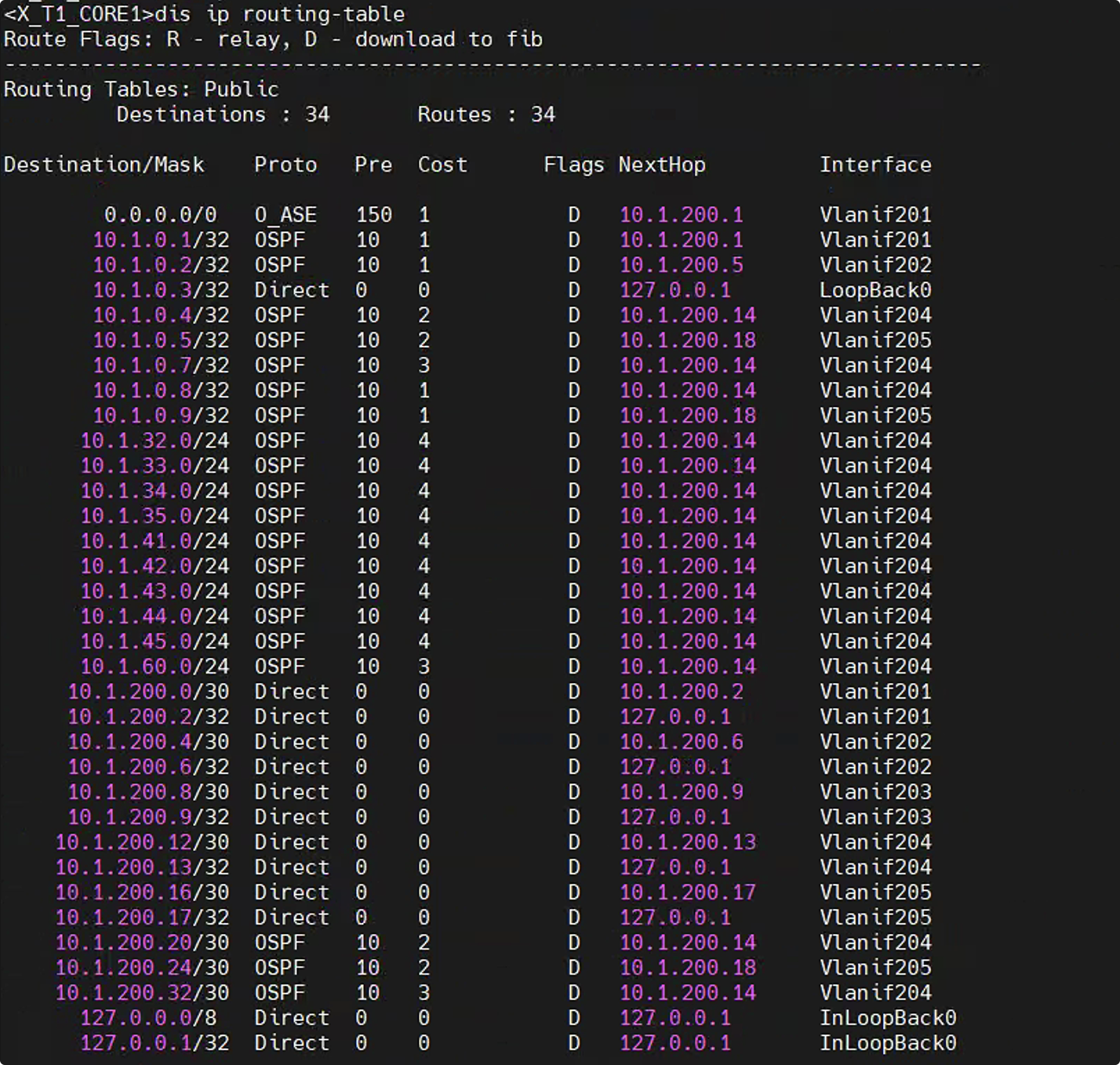
core1 display ip routing-table vpn-instance
下面这个图是我做的,不一定对,稍后对一下老师的答案
需求 1.3.2.4
使用 IP-Prefix 作为过滤器进行路由过滤,Employee 与 Guest 之间不学习对方终端所在网段的明细路由与对应的三类 LSA
在 X_T1_CORE1 上创建前缀列表,Emplyee 与 Guest
# 把Employee有线无线的网段deny掉,防止学习到3类LSA
ip ip-perfix Employee deny 10.1.11.0 24
ip ip-perfix Employee deny 10.1.12.0 24
ip ip-perfix Employee deny 10.1.13.0 24
ip ip-perfix Employee deny 10.1.14.0 24
ip ip-perfix Employee deny 10.1.15.0 24
ip ip-perfix Employee deny 10.1.21.0 24
ip ip-perfix Employee deny 10.1.22.0 24
ip ip-perfix Employee deny 10.1.23.0 24
ip ip-perfix Employee deny 10.1.24.0 24
ip ip-perfix Employee deny 10.1.25.0 24
ip ip-perfix Employee deny 10.1.31.0 24
ip ip-perfix Employee deny 10.1.32.0 24
ip ip-perfix Employee deny 10.1.33.0 24
ip ip-perfix Employee deny 10.1.34.0 24
ip ip-perfix Employee deny 10.1.35.0 24
ip ip-perfix Employee deny 10.1.41.0 24
ip ip-perfix Employee deny 10.1.42.0 24
ip ip-perfix Employee deny 10.1.43.0 24
ip ip-perfix Employee deny 10.1.44.0 24
ip ip-perfix Employee deny 10.1.45.0 24
ip ip-perfix Employee deny 10.1.51.0 24
ip ip-perfix Employee deny 10.1.52.0 24
ip ip-perfix Employee deny 10.1.53.0 24
ip ip-perfix Employee deny 10.1.54.0 24
ip ip-perfix Employee deny 10.1.55.0 24
ip ip-perfix Employee deny 10.1.60.0 24
# Employee允许所有
ip ip-perfix Employee permit 0.0.0.0 0 less-euqal 32

# 把Employee有线无线的网段deny掉,防止学习到3类LSA
ip ip-perfix Guest deny 10.1.101.0 24
ip ip-perfix Guest deny 10.1.102.0 24
ip ip-perfix Guest deny 10.1.103.0 24
ip ip-perfix Guest deny 10.1.104.0 24
ip ip-perfix Guest deny 10.1.105.0 24
# Guest允许所有
ip ip-perfix Guest permit 0.0.0.0 0 less-equal 32

# 把ip-prefix抓取到的路由,在对方区域引入过滤掉
ospf 1
area 1
filter ip-prefix Guest import
area 2
filter ip-prefix Employee import
需求 1.3.3
在不使用策略路由的前提下,跨 OSPF 区域的流须经过防火墙
在 X_T1_FW1 的 OSPF 进程下,关闭 OSPF 的防环检测
ospf 2
vpn-instance-capability simple
ospf 3
vpn-instance-capability simple
在 X_T1_CORE1 的 OSPF 进程下,关闭 OSPF 的防环检测
ospf 2
vpn-instance-capability simple
ospf 3
vpn-instance-capability simple
1.4 WLAN 扩容需求
X_T1_AP1 已在 AC 上线且正常提供无线服务,X_T2_AP1 和 X_T1_AP1 在相同管理 VLAN 提供相同的无线服务,即延续当前的 WLAN 相关配置
- 内部无线用户使用的 SSID 为 X_Employee_001,密码为 Huawei@123。
- 外部无线用户使用的 SSID 为 X_Guest_001,密码为 Huawei@123。
连接 PC5 的 WIFI:X_Employee_001,此处的 001 为机架号,华为有 20 台机架,,每台不相同
需求 1.4.1
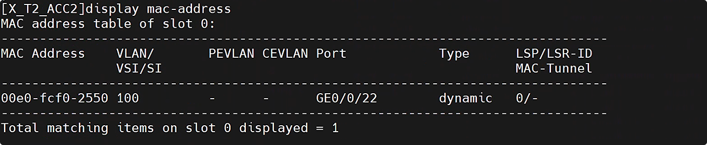
X_T2_ACC2
# 放行对AP接口和对eth1的vlan100
vlan 100
interface GigabitEthernet 0/0/22
port link-type access
port default vlan 100
display mac-address
X_T1_AC1
wlan
# 这里的mac地址是X_T2_ACC2上G0/0/22口的MAC-ADDRESS
ap-id 1 ap-mac 1122-3344-5566
ap-group X
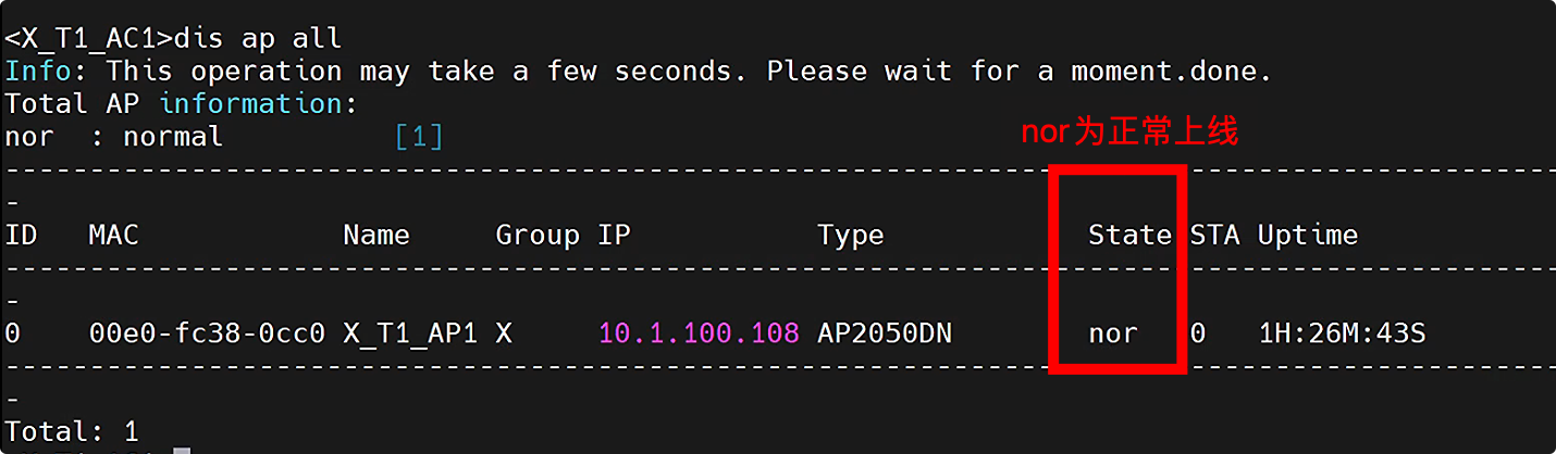
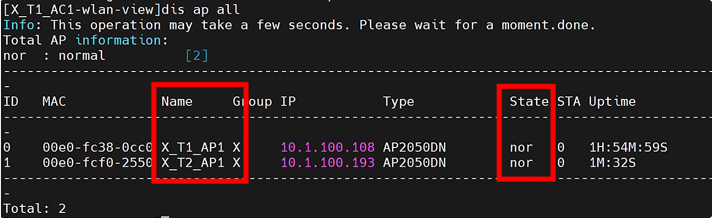
ap-name X_T2_AP1
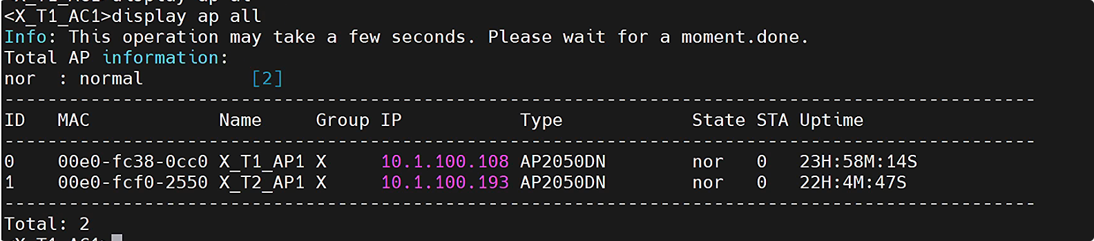
display ap all
需求 1.4.2
当前网络分别为内部与外部无线用户预留,10.1.51.0/24(VLAN51)与 10.1.101.0/24(VLAN100)经常出现由于 DHCP 服务器可用地址数不足导致用户无法正常接入无线网络的情况。1-1 扩充可用地址数量,同时还需尽量保证同意用户接入网络时,IP 地址不发生改变。
X_T1_AC1
vlan batch 51 to 55 101 to 105

interface GigabitEthernet 0/0/1
port trunk allow-pass vlan 51 to 55 101 to 105 100 203

# 创建vlan,并配置vlanl pool,同时放行业务vlan
vlan pool employee-wifi
vlan 51 to 55
assignment hash
vlan pool guest-wifi
vlan 101 to 105
assignment hash

# 将vlan pool 应用到vap模板下
wlan
vap-profile name employee
service-vlan vlan-pool employee-wifi
Y
vap-profile name guest
service-vlan vlan-pool guest-wifi
Y
X_T1_CORE1
此处做脚本,display cu 查看到以下配置,复制到 txt 中
对 # 进行替换,比如 51~55 # 替换为 vpn-instance Employee,比如 101~105 # 替换为 vpn-instance Guest
interface GigabitEthernet 0/0/3
port trunk allow-pass vlan 51 to 55 101 to 105 100 203


# 11~15,21~25,31~35,41~45
ip pool wired_finance1
 vpn-instance Employee
 gateway-list 10.1.31.254
 network 10.1.31.0 mask 255.255.255.0
ip pool wired_finance2
 vpn-instance Employee
 gateway-list 10.1.32.254
 network 10.1.32.0 mask 255.255.255.0
ip pool wired_finance3
 vpn-instance Employee
 gateway-list 10.1.33.254
 network 10.1.33.0 mask 255.255.255.0
ip pool wired_finance4
 vpn-instance Employee
 gateway-list 10.1.34.254
 network 10.1.34.0 mask 255.255.255.0
ip pool wired_finance5
 vpn-instance Employee
 gateway-list 10.1.35.254
 network 10.1.35.0 mask 255.255.255.0
ip pool wired_hr1
 vpn-instance Employee
 gateway-list 10.1.41.254
 network 10.1.41.0 mask 255.255.255.0
ip pool wired_hr2
 vpn-instance Employee
 gateway-list 10.1.42.254
 network 10.1.42.0 mask 255.255.255.0
ip pool wired_hr3
 vpn-instance Employee
 gateway-list 10.1.43.254
 network 10.1.43.0 mask 255.255.255.0
ip pool wired_hr4
 vpn-instance Employee
 gateway-list 10.1.44.254
 network 10.1.44.0 mask 255.255.255.0
ip pool wired_hr5
 vpn-instance Employee
 gateway-list 10.1.45.254
 network 10.1.45.0 mask 255.255.255.0
ip pool wired_market1
 vpn-instance Employee
 gateway-list 10.1.11.254
 network 10.1.11.0 mask 255.255.255.0
ip pool wired_market2
 vpn-instance Employee
 gateway-list 10.1.12.254
 network 10.1.12.0 mask 255.255.255.0
ip pool wired_market3
 vpn-instance Employee
 gateway-list 10.1.13.254
 network 10.1.13.0 mask 255.255.255.0
ip pool wired_market4
 vpn-instance Employee
 gateway-list 10.1.14.254
 network 10.1.14.0 mask 255.255.255.0
ip pool wired_market5
 vpn-instance Employee
 gateway-list 10.1.15.254
 network 10.1.15.0 mask 255.255.255.0
ip pool wired_procurement1
 vpn-instance Employee
 gateway-list 10.1.21.254
 network 10.1.21.0 mask 255.255.255.0
ip pool wired_procurement2
 vpn-instance Employee
 gateway-list 10.1.22.254
 network 10.1.22.0 mask 255.255.255.0
ip pool wired_procurement3
 vpn-instance Employee
 gateway-list 10.1.23.254
 network 10.1.23.0 mask 255.255.255.0
ip pool wired_procurement4
 vpn-instance Employee
 gateway-list 10.1.24.254
 network 10.1.24.0 mask 255.255.255.0
ip pool wired_procurement5
 vpn-instance Employee
 gateway-list 10.1.25.254
 network 10.1.25.0 mask 255.255.255.0

ip pool wirelees_employee1
vpn-instance Employee
gateway-list 10.1.51.254
network 10.1.51.0 mask 255.255.255.0
ip pool wirelees_employee2
vpn-instance Employee
gateway-list 10.1.52.254
network 10.1.52.0 mask 255.255.255.0
ip pool wirelees_employee3
vpn-instance Employee
gateway-list 10.1.53.254
network 10.1.53.0 mask 255.255.255.0
ip pool wirelees_employee4
vpn-instance Employee
gateway-list 10.1.54.254
network 10.1.54.0 mask 255.255.255.0
ip pool wirelees_employee5
vpn-instance Employee
gateway-list 10.1.55.254
network 10.1.55.0 mask 255.255.255.0

ip pool wirelees_guest1
vpn-instance Guest
gateway-list 10.1.101.254
network 10.1.101.0 mask 255.255.255.0
ip pool wirelees_guest2
vpn-instance Guest
gateway-list 10.1.102.254
network 10.1.102.0 mask 255.255.255.0
ip pool wirelees_guest3
vpn-instance Guest
gateway-list 10.1.103.254
network 10.1.103.0 mask 255.255.255.0
ip pool wirelees_guest4
vpn-instance Guest
gateway-list 10.1.104.254
network 10.1.104.0 mask 255.255.255.0
ip pool wirelees_guest5
vpn-instance Guest
gateway-list 10.1.105.254
network 10.1.105.0 mask 255.255.255.0
# 在51 to 55 101 to 105,208 209接口下开启全局dhcp
dhcp enable
interface vlanif 51
dhcp select global
interface vlanif 52
dhcp select global
interface vlanif 53
dhcp select global
interface vlanif 54
dhcp select global
interface vlanif 55
dhcp select global
# 60 不做

interface vlanif 101
dhcp select global
interface vlanif 102
dhcp select global
interface vlanif 103
dhcp select global
interface vlanif 104
dhcp select global
interface vlanif 105
dhcp select global

interface vlanif 208
dhcp select global
interface vlanif 209
dhcp select global
然后到 PC 上连接 wifi,cmd ipconfig
在 X_Employee_007 上查看到的无线网卡应该是,51~55 网段
在 X_Guest_007 上查看到的无线网卡应该是,101~105 网段
1.5 出口网络需求
需求 1.5.1
新增出口路由 X_T1_Export2,采用双 Internet 线路实现上网流量的负载分担
- GE0/0/9 接口采用静态配置 IP 地址(10.255.3.1/24),网关为 10.255.3.254
- GE0/0/10 接口采用静态配置 IP 地址(10.255.4.1/24),网关为 10.255.4.254
X_Export 2 配置 IP 地址和缺省路由
#                模拟器上的g0/0/1
interface GigabitEthernet 0/0/9
ip address 10.255.3.1 24

#                模拟器上的g0/0/0
interface GigabitEthernet 0/0/10
ip address 10.255.4.1 24

ip route-static 0.0.0.0 0 10.255.3.254
ip route-static 0.0.0.0 0 10.255.4.254
需求 1.5.2
所有用户通过 X_T_Expoet2 路由器访问 Internet 时,需要通过 NAT 替换私网 IP 地址
- 对所有通过防火墙策略的 IP 报文进行源地址与端口转换
- Export_2 的 GE0/0/9 使用当前接口 IP 地址作为转换后的地址
- Export_2 的 GE0/0/10 使用地址池(10.255.4.2-10.255.4.100)替换私网 IP 地址和端口
- x 园区内网服务器(10.1.60.101)向外提供 WEB 服务(端口号 80),公网用户通过 10.255.4.1 的 8081 号端口访问该服务
X_Export 2 上配置 ACL
# 1)对所有通过防火全策略的IP报文进行源地址与端口转换
acl 2000
rule permit

# 2)GE0/0/9使用当前接口IP地址作为转换后的地址,模拟器上的GE0/0/1口
interface GigabitEthernet 0/0/9
 nat outbound 2000
quit
nat address-group 1 10.255.4.2 10.255.4.100

# 3)Export2的GE0/0/10使用地址池(10.255.4.2-10.255.4.100)替换私网IP地址和端口
# 模拟器上的GE0/0/0口,配置NAPT功能
interface GigabitEthernet 0/0/10
nat outbound 2000 address-group 1
# 4)x园区内网服务器(10.1.60.101:80)向外提供WEB服务,公网用户通过10.255.4.1:8081访问该服务
nat server protocol tcp global current-interface 8081 inside 10.1.60.101 80
X_T1_FW1 的虚拟系统 Employee 中放行 HTTP 流量
Switch vsys Employee
security-policy
rule name permit-untrust-trust-ser60.101
source-zone untrust
destination-zone trust
destination-address 10.1.60.101 mask 255.255.255.255
service http
action permit
1.6 准入认证
- 为保证“端到端”网络安全,需要对除服务器外的所有有线终端进行认证,
- 有线终端中,PC 支持 802.1x 认证,打印机及 IP 电话等哑终端不支持,已知当前采用的接入交换机不支持 802.1x 认证与策略联动功能
- 汇聚交换机与认证服务器之间采用 RADIUS 协议进行交互,服务器地址为 10.1.60.2。使用默认端口号进行认证、授权和计费,秘钥为 Huawei@123
- 所有涉及到的模版均命名为 Employee
- 认证域为 employee,且不允许用户使用其他域
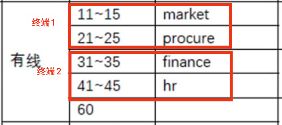
- RADIUS 服务器通过 VLAN 池名称方式下发用户的 VLAN 信息,VLAN 池名称参考表 1-1
- 对于所有 AP 设备,需要根据 AP 的 MAC 地址,强制其到 ap_noauthen 域进行认证,且该域的认证模式为 none
- 用户信息与对应的授权信息已在认证与授权服务器上做了配置,考生无需关心,用户名密码信息:
hr/Huawei@123、market/Huawei@123、produre/Huawei@123、finance/Huawei@123、
需求 1.6.1.1
四个接入交换机(X_T1_ACC1/2,X_T2_ACC1/2)
在四个接入设备配置 dot1x 透传功能
# 0180-c200-0003这个目的mac地址是固定的,后面改成group-mac目的组播地址(自定义无限制)
l2protocol-tunnel user-defined-protocol dot1x protocol-mac 0180-c200-0003 group-mac 0100-0000-0002

# 模拟器上用port-group group-member GigabitEthernet 0/0/1 to GigabitEthernet 0/0/20
interface rang GigabitEthernet 0/0/1 to GigabitEthernet 0/0/20
l2protocol-tunnel user-defined-protocol dot1x enable

interface Eth-trunk 1
l2protocol-tunnel user-defined-protocol dot1x enable
1.6.1.2&3
a. 汇聚交换机与认证服务器之间采用 RADIUS 协议进行交互,服务器地址为 10.1.60.2。使用默认端口号进行认证、授权和计费,秘钥为 Huawei@123
b. 所有涉及到的模版均命名为 Employee
在 X_T1_AGG1 和 X_T2_AGG1 两个汇聚上
radius-server template employee 模板
radius-server authentication 10.1.60.2 1812 认证服务器
radius-server accounting 10.1.60.2 1813 计费服务器
radius-server shared-key cipher Huawei@123
quit
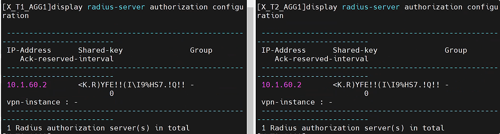
radius-server authorization 10.1.60.2 shared-key cipher Huawei@123 授权
display radius-server authorization configuration
1.6.1.4
认证域为 employee,且不允许用户使用其他域
X_T1_AGG1 和 X_T2_AGG1 配置 AAA 认证信息
aaa
authentication-scheme employee    # 认证
 authentication-mode radius
quit
authorization-scheme employee    # 授权
 authorization-mode none
quit
accounting-scheme employee       # 计费
 accounting-mode radius
quit
domain employee                 # 认证域
 authentication-scheme employee
 authorization-scheme employee
 accounting-scheme employee
 radius-server employee
X_T1_AGG1 和 X_T2_AGG1 配置 MAC、dot1x、认证模板(模拟器配不了)
dot1x-access-profile name employee          # dot1x接入模板
quit
mac-access-profile name employee            # mac接入模板
quit
authentication-profile name employee        # 认证模版
 mac-access-profile employee
 dot1x-access-profile employee
 authentication dot1x-mac-bypass                # mac旁路
 access-domain employee force                   # 用户强制域
X_T1_AGG1 和 X_T2_AGG1 的下游接口,调用认证模板(模拟器配不了)
interface Eth-trunk 2                               # 下游汇聚接口 调用认证模板
authenticantion-profile employee
interface Eth-trunk 3                               # 下游汇聚接口 调用认证模板
authenticantion-profile employee
1.6.1.5(模拟器做不了)
RADIUS 服务器通过 VLAN 池名称方式下发用户的 VLAN 信息,VLAN 池名称参考表 1-1
X_T1_AGG1 上创建用户授权的 vlan pool
vlan pool market
vlan 11 to 15

vlan pool procure
vlan 21 to 25
X_T2_AGG1 上创建用户授权的 vlan pool
vlan pool finance
vlan 31 to 35

vlan pool hr
vlan 41 to 45
1.6.2
对于所有 AP 设备,需要根据 AP 的 MAC 地址,强制其到 ap_noauthen 域进行认证,且该域的认证模式为 none
X_T1_AGG1 和 X_T2_AGG1 配置 AP 免认证信息
aaa
authentication-scheme ap-noauthen           认证模板
authentication-mode none                    认证模式 空
y
q

domain ap-noauthen
authentication-scheme ap-noauthen
在 X_T1_AC1 获取 AP 的 MAC 地址
display ap all
X_T1_AGG1(模拟器做不了)
# 后面的ffff-ffff-ffff是掩码,不是填地址的
domain ap-noauthen mac-authen force mac-address <T1_AP1的MAC地址> mask ffff-ffff-ffff
X_T2_AGG1(模拟器做不了)
domain ap-noauthen mac-authen force mac-address <T2_AP1的MAC地址> mask ffff-ffff-ffff
1.6.3
用户信息与对应的授权信息已在认证与授权服务器上做了配置,考生无需关心,用户名密码信息:
hr/Huawei@123、market/Huawei@123、produre/Huawei@123、finance/Huawei@123、
X_T1_AGG1 上配置 DHCP Relay 功能
dhcp enable
# 11 to 15
interface vlanif 11
dhcp select relay
# dhcp中继服务器Core 1的vlan 208对接T1楼
dhcp relay server-ip 10.1.200.29
interface vlanif 12
dhcp select relay
dhcp relay server-ip 10.1.200.29
interface vlanif 13
dhcp select relay
dhcp relay server-ip 10.1.200.29
interface vlanif 14
dhcp select relay
dhcp relay server-ip 10.1.200.29
interface vlanif 15
dhcp select relay
dhcp relay server-ip 10.1.200.29

# 21 to 25
interface vlanif 21
dhcp select relay
dhcp relay server-ip 10.1.200.29
interface vlanif 22
dhcp select relay
dhcp relay server-ip 10.1.200.29
interface vlanif 23
dhcp select relay
dhcp relay server-ip 10.1.200.29
interface vlanif 24
dhcp select relay
dhcp relay server-ip 10.1.200.29
interface vlanif 25
dhcp select relay
dhcp relay server-ip 10.1.200.29
X_T2_AGG1 配置 DHCP Relay 功能
dhcp enable
# 31 to 35
interface vlanif 31
dhcp select relay
# dhcp中继服务器Core 1的vlan 209对接T1楼
dhcp relay server-ip 10.1.200.33
interface vlanif 32
dhcp select relay
dhcp relay server-ip 10.1.200.33
interface vlanif 33
dhcp select relay
dhcp relay server-ip 10.1.200.33
interface vlanif 34
dhcp select relay
dhcp relay server-ip 10.1.200.33
interface vlanif 35
dhcp select relay
dhcp relay server-ip 10.1.200.33
# 41 to 45
interface vlanif 41
dhcp select relay
dhcp relay server-ip 10.1.200.33
interface vlanif 42
dhcp select relay
dhcp relay server-ip 10.1.200.33
interface vlanif 43
dhcp select relay
dhcp relay server-ip 10.1.200.33
interface vlanif 44
dhcp select relay
dhcp relay server-ip 10.1.200.33
interface vlanif 45
dhcp select relay
dhcp relay server-ip 10.1.200.33
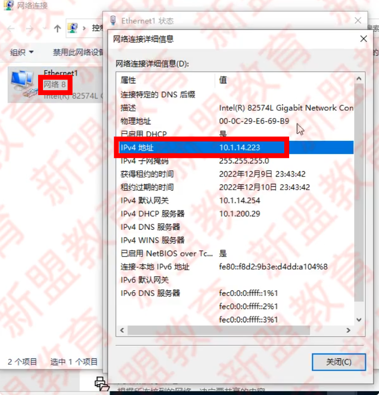
打开 terminal01,网络连接->Ethernet1 的状态-> 属性-> 身份认证-> 其他设置-> 改成用户身份认证-> 保存凭据
账号:market,密码:Huawei@123,账号:produce,密码:Huawei@123,点击确定,禁用再启用网卡,打开 cmd,ipconfig,
打开 terminal02,网络连接->Ethernet1 的状态-> 属性-> 身份认证-> 其他设置-> 改成用户身份认证-> 保存凭据
账号:hr,密码:Huawei@123,账号:fiance,密码:Huawei@123,点击确定,重启网卡,打开 cmd,ipconfig,
比如 terminal1 获得到了 14 网段就是对了,因为它属于 market
1.7 网络安全需求
需求交换机的策略路由没有办法配置,或者通过流策略配置之后是不生
1.7.1.1
防火墙配置安全策略实现用户访问控制的权限
- 仅采购部、市场部、内部无线用户、外部无线用户可以访问 Internet
- 内部无线用户仅可以访问服务器网段的某服务器,其 IP 地址为 10.1.60.100
- 外部无线用户仅可以访问服务器网段中的 HTTP 服务(服务名为 Guest_Service)IP 地址为 10.1.60.99,端口号为 3389(TCP)
X_T1_FW1 配置安全策略允许访问 internet
sw vsys Employee
# Employee系统下,允许市场、采购、employee无线访问Internet
ip address-set market type group
address 0 10.1.11.0 mask 24
address 1 10.1.12.0 mask 24
address 2 10.1.13.0 mask 24
address 3 10.1.14.0 mask 24
address 4 10.1.15.0 mask 24
ip address-set procure type group
address 0 10.1.21.0 mask 24
address 1 10.1.22.0 mask 24
address 2 10.1.23.0 mask 24
address 3 10.1.24.0 mask 24
address 4 10.1.25.0 mask 24
ip address-set employee-wifi type group
address 0 10.1.51.0 mask 24
address 1 10.1.52.0 mask 24
address 2 10.1.53.0 mask 24
address 3 10.1.54.0 mask 24
address 4 10.1.55.0 mask 24

security-policy
rule name permit-trust-untrust-internet
source-zone trust
destintion-zone untrust
source-address address-set market
source-address address-set procure
source-address address-set employee-wifi
action permit
return
sys

sw vsys Guest
# 在Guest系统下,允许guest-wifi
ip address-set guest-wifi type group
address 0 10.1.101.0 mask 24
address 1 10.1.102.0 mask 24
address 2 10.1.103.0 mask 24
address 3 10.1.104.0 mask 24
address 4 10.1.105.0 mask 24

security-policy
rule name permit-trust-untrust-internet
source-zone trust
destintion-zone untrust
source-address address-set guest-wifi
action permit
1.7.1.2
内部用户仅可以访问服务器网段的某服务器,其 IP 地址为 10.1.60.100
X_T1_CORE1 将内部访问服务器网段的流量,重定向到虚拟系统 employee
acl 3000
# 允许源51~55网段(内部wifi)到目的60网段
rule 5 permit ip source 10.1.51.0 0.0.0.255 destination 10.1.60.0 0.0.0.255
rule 10 permit ip source 10.1.52.0 0.0.0.255 destination 10.1.60.0 0.0.0.255
rule 15 permit ip source 10.1.53.0 0.0.0.255 destination 10.1.60.0 0.0.0.255
rule 20 permit ip source 10.1.54.0 0.0.0.255 destination 10.1.60.0 0.0.0.255
rule 25 permit ip source 10.1.55.0 0.0.0.255 destination 10.1.60.0 0.0.0.255
# 以下模拟器无法配置
# 51~55网段的流量到达core1,下一跳指向FW1的VLANif204(10.1.200.14)
interface vlanif 51
traffic-redirect inbound acl 3000 ip-next-hop 10.1.200.14
interface vlanif 52
traffic-redirect inbound acl 3000 ip-next-hop 10.1.200.14
interface vlanif 53
traffic-redirect inbound acl 3000 ip-next-hop 10.1.200.14
interface vlanif 54
traffic-redirect inbound acl 3000 ip-next-hop 10.1.200.14
interface vlanif 55
traffic-redirect inbound acl 3000 ip-next-hop 10.1.200.14
X_T1_FW1 虚拟系统 Employee 方向访问服务 60.100 的流量
sw vsys Employee
security-policy
rule name permit-untrust-trust-60.100
source-zone untrust
destination-zone trust
source-address address employee-wifi
destination-addresss 10.1.60.100 32
action permit
1.7.1.3
外部无线用户仅可以访问服务器网段中的 HTTP 服务(服务名为 Guest_Service)IP 地址为 10.1.60.99,端口号为 3389(TCP)
外部访问内部,trust-untrust
X_T1_FW1 在虚拟系统 Guest 中配置自定义服务,允许外部无线访问 60.99 的 TCP3389
sw vsys Guest
ip service-set Guest_Service type object
service protocol tcp destination-port 3389
q
security-policy
rule name permit-trust-untrust-60.99
source-zone trust
destination-zone untrust
source-address address guest-wifi
destination-addresss 10.1.60.99 32
service Guest_Service
y
action permit

# 其余到达10.1.60.0/24网段的都拒绝
quit
rule name deny-trust-untrust-other-server
source-zone trust
destination-zone untrust
source-address address guest-wifi
destination-addresss 10.1.60.0 24
action deny
sw vsys Employee

ip service-set Guest_Service type object
service protocol tcp destination-port 3389
quit
ip address-set guest-wifi type group
address 10.1.101.0 mask 24
address 10.1.102.0 mask 24
address 10.1.103.0 mask 24
address 10.1.104.0 mask 24
address 10.1.105.0 mask 24

security-policy
rule name permit-untrust-trust-60.99
source-zone untrust
destination-zone trust
source-address address guest-wifi
destination-addresss 10.1.60.99 32
service Guest_Service
action permit
优化,把 internet 移到底部
sw vsys Employee
security-policy
rule move permit-trust-untrust-internet bottom

sw vsys Guest
security-policy
rule move permit-trust-untrust-internet bottom
1.7.3.1
外部无线用户访问 Guest Service 服务的流量需要直接在 Guest 和 Employee 两个虚拟系统
- Guest 和 Employee 两个虚拟系统的 Virtual-if 属于 untrust 安全域,IP 地址为 10.1.200.254/32 与 10.1.200.253/32
X_T1_FW1 在虚拟系统为 Virtual-if 配置 IP 地址,并加入安全区域
sw vsys Employee
# display ip int b
# 此处的X编号是查看IP地址表后的VLANif编号,比如virtual-if 1
firewall zone untrust
add interface virtual-if 1
quit
interface virtual-if 1
ip address 10.1.200.253 32
return
sys
sw vsys Guest
# display ip int b
# 此处的X编号是查看IP地址表后的VLANif编号
firewall zone untrust
add interface virtual-if 2
quit
interface virtual-if 2
ip address 10.1.200.254 32
1.7.3.2
- 仅当外部无线用户访问 10.1.60.99 时,流量直接在虚拟系统之间转发
X_T1_FW1
ip route-static vpn-instance Guest 10.1.60.99 32 vpn-instance Employee
ip route-static vpn-instance Employee 10.1.101.0 24 vpn-instance Guest
ip route-static vpn-instance Employee 10.1.102.0 24 vpn-instance Guest
ip route-static vpn-instance Employee 10.1.103.0 24 vpn-instance Guest
ip route-static vpn-instance Employee 10.1.104.0 24 vpn-instance Guest
ip route-static vpn-instance Employee 10.1.105.0 24 vpn-instance Guest
1.9 结果验证
用 windows 截图软件,截全屏即可,创建一个文件夹把截图文件放进去
Temimal 05 连接不同 Wi-Fi 之后,可以访问相应的网络资源。
- 连接外部用户对应无线信号后,telnet 10.1.60.99 的 3389 端口(截图):PING10.255.1.254(截图)。
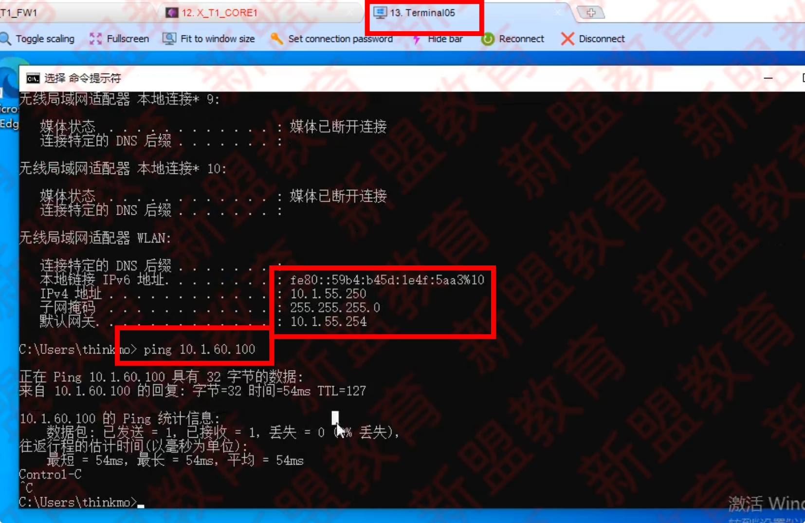
- 连接内部用户对应无线信号后,PING 10.1.60.100 (截图):PING 101.60.99(截图)
1)连接 Guest_WIFI
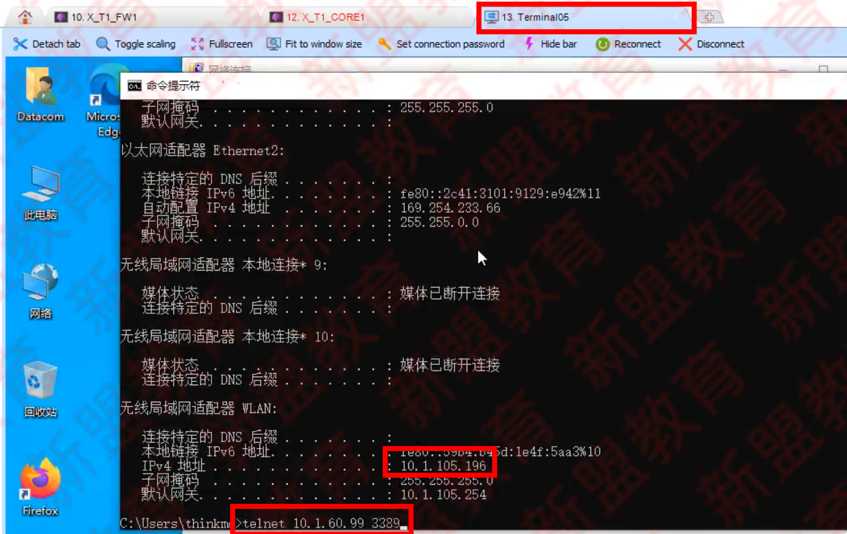

Ctrl+}退出
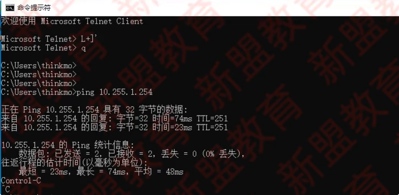
2)连接 Employee_WIFI
ping 通
ping 不通(正常)

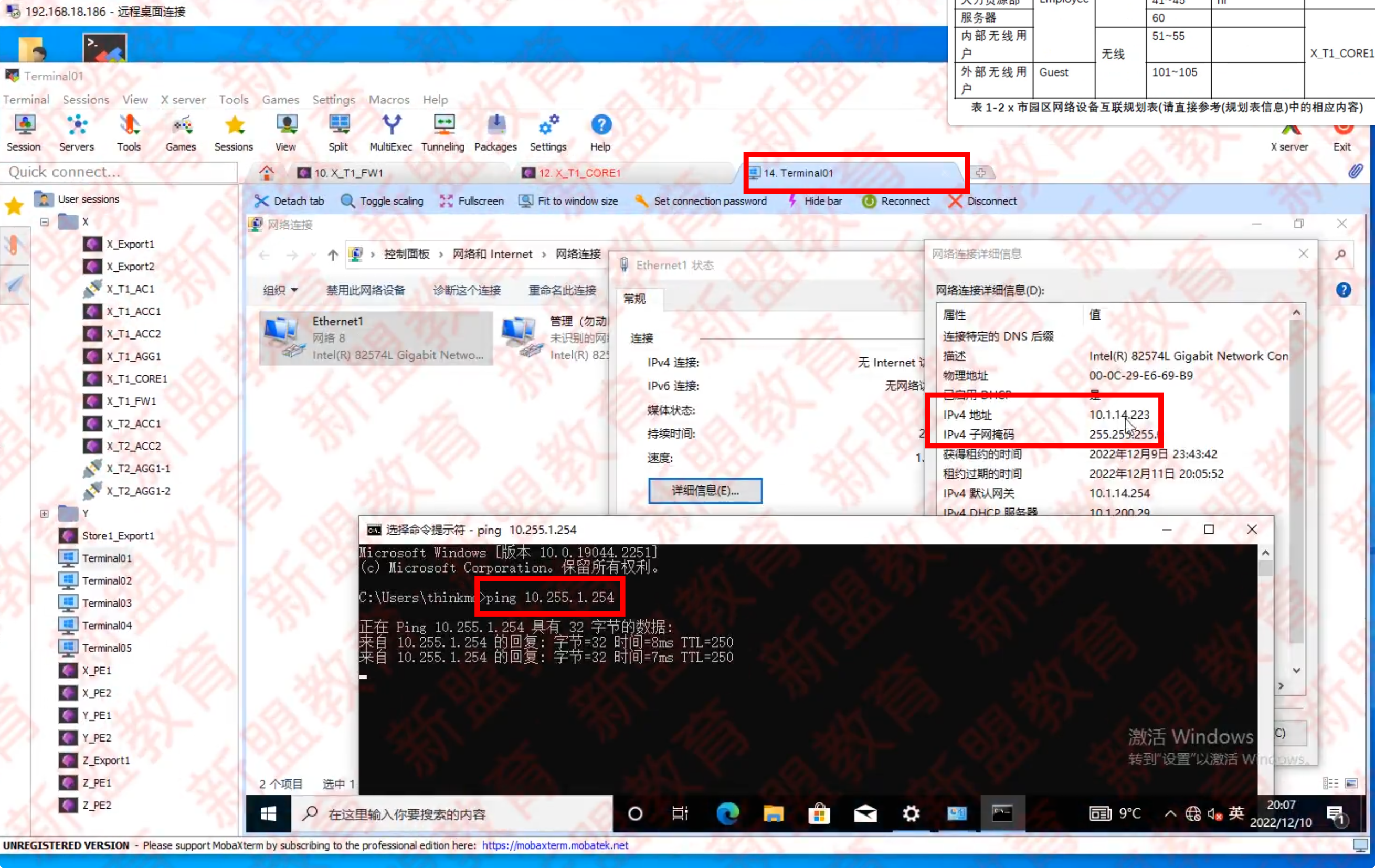
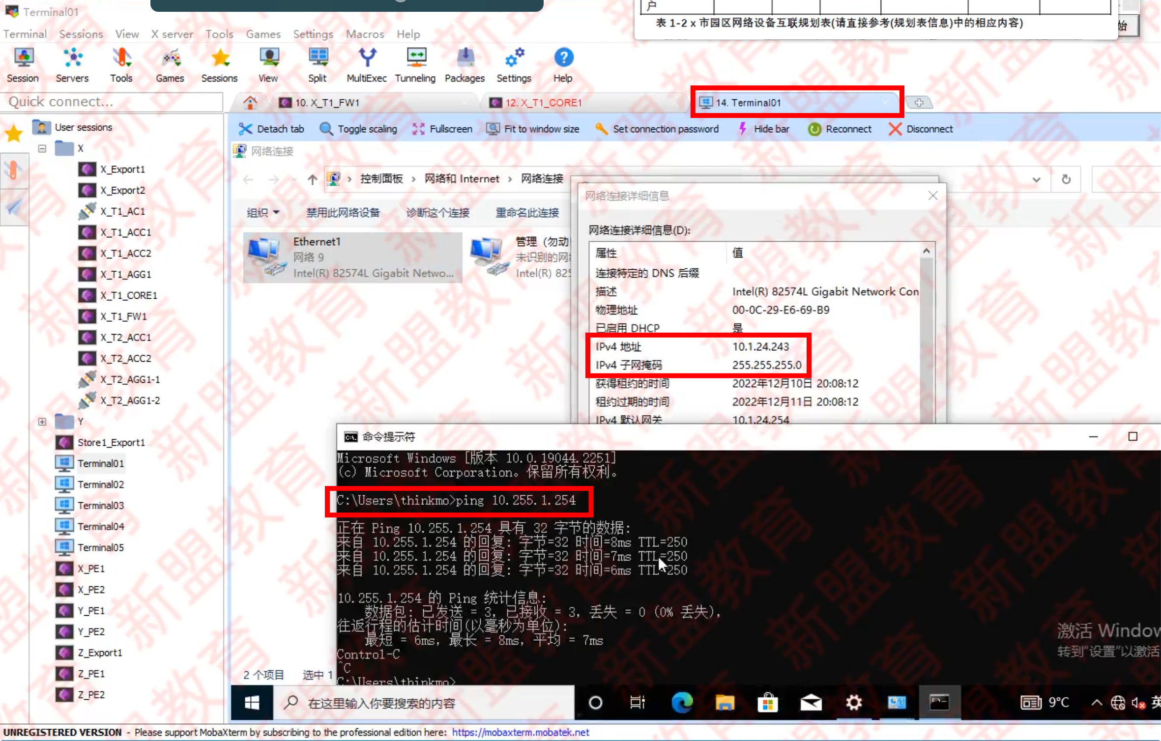
有线用户 Terminnlo1 和 Terminalo2 通过认证之后可以访问到相应的网络资源。
- Terminal01 PING 10.255,1.254(截图)。
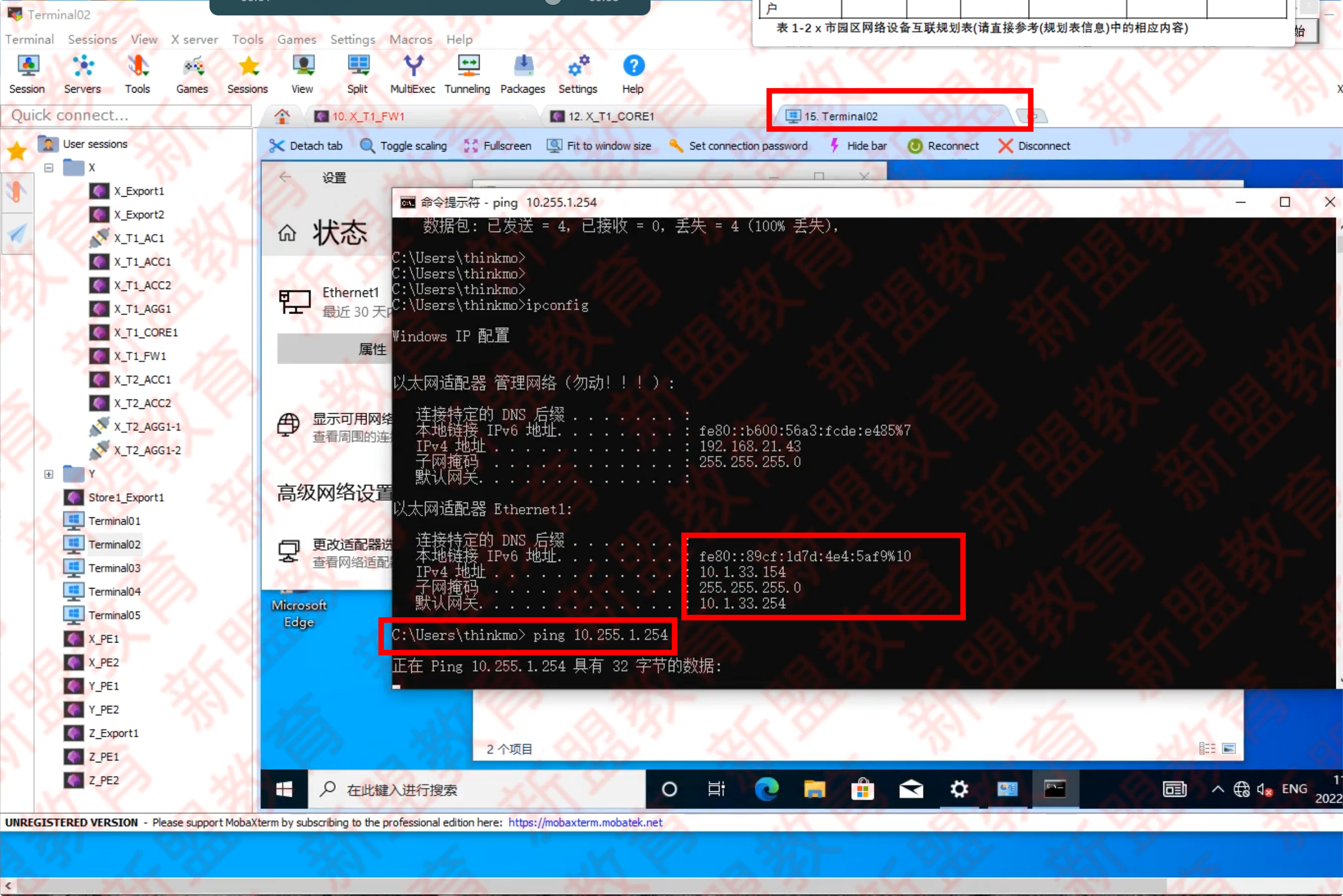
- Terminal02 PING 10.255.1.254 (截图)。
Terminal01
market 用户,获得的地址是 10.1.11~15.254 网段
ping 通
登陆 produce 用户
Terminal02
hr,ping 不通才是对的
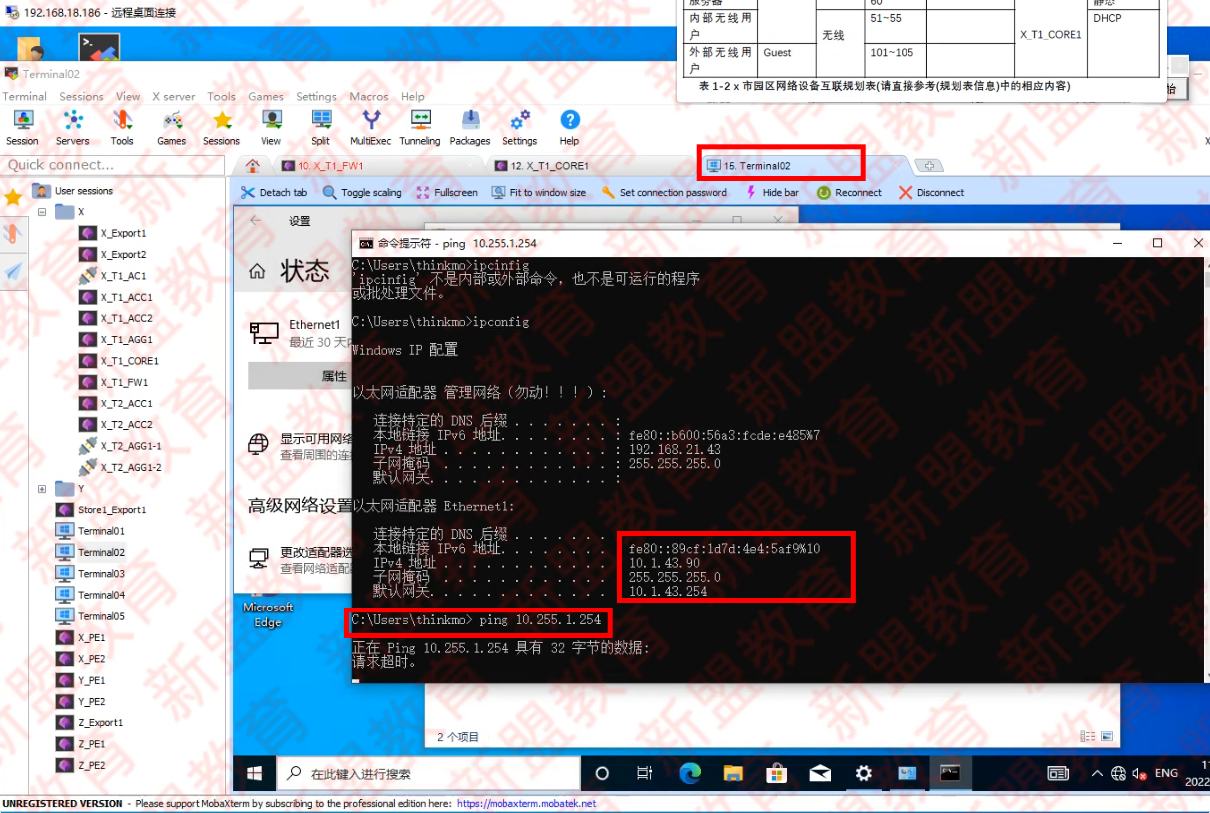
finance,ping 不通才是对的